SUMMARY: The chapter on Alternating Current in Class 12 Physics covers the principles, mathematical representation, and applications of AC circuits. KEY TOPICS: AC voltage and current, peak and RMS values, phase difference, reactance and impedance, LC oscillations, resonance in AC circuits, power in AC circuits, transformers, power factor, LC and RLC circuits.
The rms value of an alternating current with peak value I₀ is:
AI₀
BI₀/2
CI₀/√2
DI₀√2
Check answerHide answer
Correct answer: Option 3 — I₀/√2
Q31 Mark
The reactance of a pure inductor in an AC circuit is:
A1/(ωC)
BωL
C1/(ωL)
DωC
Check answerHide answer
Correct answer: Option 2 — ωL
Q41 Mark
At resonance in an LCR series circuit:
AX_L = X_C
BX_L > X_C
CX_L < X_C
DBoth reactances are zero
Check answerHide answer
Correct answer: Option 1 — X_L = X_C
Q51 Mark
Power dissipated in a pure inductor is:
AMaximum
BMinimum
CZero
DV²/2L
Check answerHide answer
Correct answer: Option 3 — Zero
Short Answer Questions5 questions
Q63 Marks
Define rms (root mean square) value of alternating current.
View sample solutionHide solution
The rms (root mean square) value of an alternating current is the value of steady DC that would produce the same heat in a resistor in the same time. For sinusoidal AC: I_rms = I₀/√2 ≈ 0.707 I₀ where I₀ is the peak current. SI unit: ampere (A). Average AC value over a cycle is zero (sine averages to zero) but the rms is positive — used for power calculations.
Q73 Marks
What is reactance? Distinguish between inductive and capacitive reactance.
View sample solutionHide solution
Reactance is the opposition offered to AC by an inductor or capacitor. Inductive reactance X_L = ωL — increases with frequency. Causes current to lag voltage by π/2. Capacitive reactance X_C = 1/(ωC) — decreases with frequency. Causes current to lead voltage by π/2. Both have units of ohm (Ω). Unlike resistance reactance dissipates no power.
Q83 Marks
Calculate the reactance of (a) a 0.5 H inductor and (b) a 10 μF capacitor at 50 Hz.
Impedance Z is the total opposition to AC in an LCR series circuit. It includes the resistance R inductive reactance X_L = ωL and capacitive reactance X_C = 1/(ωC). Z = √(R² + (X_L − X_C)²). The current lags or leads the voltage depending on whether X_L > X_C (lagging) or X_L < X_C (leading). At resonance X_L = X_C and Z = R (minimum). SI unit: ohm.
Q103 Marks
A transformer has 100 turns in the primary and 1000 turns in the secondary. If the primary voltage is 220 V calculate the secondary voltage.
View sample solutionHide solution
For an ideal transformer: V_p/V_s = N_p/N_s ⇒ V_s = V_p × N_s/N_p = 220 × 1000/100 = 2200 V. This is a step-up transformer (voltage increased by factor 10). Primary current is 10× the secondary current (assuming 100% efficiency).
Long Answer Questions6 questions
Q116 Marks
Discuss the working of a transformer and derive its turn ratio.
View sample solutionHide solution
A transformer has two coils — primary (N_p turns) and secondary (N_s turns) — wound on a common laminated soft-iron core. AC in the primary creates a changing magnetic flux in the core which links both coils. By Faraday's law: EMF_p = −N_p dΦ/dt; EMF_s = −N_s dΦ/dt. Dividing: V_s/V_p = N_s/N_p (turn ratio). For an ideal transformer (no losses): power conservation gives V_p I_p = V_s I_s ⇒ I_s/I_p = N_p/N_s. Step-up: N_s > N_p increases voltage decreases current. Step-down: opposite. Used in electricity transmission (high V low I to reduce I²R losses) and household appliances.
Q126 Marks
Derive the expression for the impedance of a series LCR circuit and the condition for resonance.
View sample solutionHide solution
In a series LCR circuit driven by AC voltage V = V₀ sin(ωt) the current is I = I₀ sin(ωt − φ). The voltage across each component: V_R = IR (in phase); V_L = IX_L (leads I by π/2); V_C = IX_C (lags I by π/2). Phasor diagram: V_R along x-axis V_L upward V_C downward; total V = √(V_R² + (V_L − V_C)²) = I √(R² + (X_L − X_C)²). Hence impedance Z = √(R² + (X_L − X_C)²). Phase: tan φ = (X_L − X_C)/R. Resonance occurs when X_L = X_C: ωL = 1/(ωC) ⇒ ω₀ = 1/√(LC). At resonance: Z = R (minimum); current is maximum; circuit is purely resistive.
Q136 Marks
An AC source of 200 V 50 Hz is connected to a series LCR circuit with R = 30 Ω L = 0.1 H C = 10 μF. Find (i) impedance, (ii) current, (iii) phase angle.
Define power factor and discuss its significance in AC circuits.
View sample solutionHide solution
Power factor cos φ = R/Z is the ratio of true power (dissipated as heat) to apparent power (V_rms × I_rms). True power P = V_rms × I_rms × cos φ. Apparent power S = V_rms × I_rms. Reactive power Q = V_rms × I_rms × sin φ. For a pure resistor: cos φ = 1 (all apparent power becomes true power). For pure inductor or capacitor: cos φ = 0 (no power dissipated — sometimes called 'wattless' current). Industrial loads with low power factor (e.g. inductive motors) draw extra reactive current — utility companies penalize this. Power factor correction (parallel capacitors) brings cos φ closer to 1.
Q156 Marks
A series LCR circuit has R = 200 Ω L = 1 H C = 4 μF. Find the resonant frequency the bandwidth and the quality factor Q.
View sample solutionHide solution
Resonant angular frequency: ω₀ = 1/√(LC) = 1/√(1 × 4 × 10⁻⁶) = 1/(2 × 10⁻³) = 500 rad/s. Resonant frequency: f₀ = ω₀/(2π) = 500/(2π) ≈ 79.6 Hz. Quality factor: Q = ω₀L/R = 500 × 1/200 = 2.5. Bandwidth: Δω = R/L = 200/1 = 200 rad/s. Bandwidth in Hz: Δf = Δω/(2π) ≈ 31.8 Hz. High-Q circuit (Q > 10) is sharply resonant; low-Q is broad-band. Used in radio tuning where Q ≈ 100 selects one station out of many.
Q166 Marks
Differentiate between AC and DC in tabular form on five features.
Assertion–Reason Questions5 questions
Q171 Mark
Assertion (A): The rms value of a sinusoidal AC is I₀/√2.
Reason (R): The square root of the mean of the square of i(t) over one cycle gives this value because the average of sin² over a cycle is 1/2.
Show explanationHide explanation
Correct answer: Option 1 —
Both A and R are true, and R is the correct explanation of A.
Q181 Mark
Assertion (A): An inductor offers more opposition to high-frequency AC than to low-frequency.
Reason (R): X_L = ωL increases linearly with frequency.
Show explanationHide explanation
Correct answer: Option 1 —
Both A and R are true, and R is the correct explanation of A.
Q191 Mark
Assertion (A): At resonance the current in an LCR circuit is maximum.
Reason (R): At resonance X_L = X_C so impedance Z = R is minimum.
Show explanationHide explanation
Correct answer: Option 1 —
Both A and R are true, and R is the correct explanation of A.
Q201 Mark
Assertion (A): The power dissipated in a pure inductor is zero.
Reason (R): The phase difference between V and I is 90° so cos φ = 0 and P = VI cos φ = 0.
Show explanationHide explanation
Correct answer: Option 1 —
Both A and R are true, and R is the correct explanation of A.
Q211 Mark
Assertion (A): A step-up transformer increases voltage but decreases current.
Reason (R): Power is conserved: V_p I_p = V_s I_s; if V_s > V_p then I_s < I_p.
Show explanationHide explanation
Correct answer: Option 1 —
Both A and R are true, and R is the correct explanation of A.
Statement-Based Questions5 questions
Q221 Mark
Statement 1: The peak value of AC is √2 times the rms value.
Statement 2: The frequency of household AC in India is 50 Hz.
Show answerHide answer
Correct answer: Option 1 —
Both statements are true.
Q231 Mark
Statement 1: Inductive reactance X_L = ωL.
Statement 2: Capacitive reactance X_C = 1/(ωC).
Show answerHide answer
Correct answer: Option 1 —
Both statements are true.
Q241 Mark
Statement 1: Impedance of an LCR series circuit is Z = √(R² + (X_L − X_C)²).
Statement 2: At resonance X_L = X_C and Z = R.
Show answerHide answer
Correct answer: Option 1 —
Both statements are true.
Q251 Mark
Statement 1: A transformer steps voltage up or down.
Statement 2: It works only on AC because it requires changing flux for mutual induction.
Show answerHide answer
Correct answer: Option 1 —
Both statements are true.
Q261 Mark
Statement 1: Average power in AC circuit P = V_rms × I_rms × cos φ.
Statement 2: Cos φ is called the power factor.
Show answerHide answer
Correct answer: Option 1 —
Both statements are true.
Case Study / Passage Questions3 questions
Q273 Marks
An AC source has a peak voltage of 311 V at 50 Hz. The student wants to find (i) rms voltage (ii) angular frequency (iii) peak-to-peak voltage and (iv) the period.
The rms voltage equals:
A156 V
B220 V
C440 V
D311 V
The angular frequency equals:
A50 rad/s
B100 rad/s
C100π rad/s
D2π rad/s
Compute the period of oscillation.
Show answersHide answers
1. Option 2 — 220 V
2. Option 3 — 100π rad/s
3. V_rms = V_peak/√2 = 311/1.414 ≈ 220 V — the standard household supply in India. Angular frequency: ω = 2πf = 2π × 50 = 100π ≈ 314 rad/s. Peak-to-peak voltage: V_pp = 2V_peak = 622 V. Period: T = 1/f = 1/50 = 0.02 s = 20 ms.
Q283 Marks
A series LCR circuit has L = 0.1 H C = 10 μF R = 100 Ω connected to an AC source with adjustable frequency. The technician wants to find the resonant frequency and the maximum current at the resonance for a 220 V AC source.
The resonant frequency equals approximately:
A159 Hz
B318 Hz
C500 Hz
D1000 Hz
The maximum (resonant) current equals:
A1.1 A
B2.2 A
C4.4 A
D7 A
Why is the impedance minimum at resonance?
Show answersHide answers
1. Option 1 — 159 Hz
2. Option 2 — 2.2 A
3. Resonant angular frequency: ω₀ = 1/√(LC) = 1/√(0.1 × 10 × 10⁻⁶) = 1/√(10⁻⁶) = 1000 rad/s. Resonant frequency: f₀ = ω₀/(2π) = 1000/(2π) ≈ 159 Hz. At resonance Z = R (minimum); current is maximum. I_max = V_rms/R = 220/100 = 2.2 A. Quality factor Q = (1/R)√(L/C) = (1/100)√(0.1/10⁻⁵) = (1/100)√(10⁴) = 1 — moderate Q.
Q293 Marks
A power transformer has 2000 turns in primary and 100 turns in secondary. It is supplied with 220 V AC (rms) at 5 A. Assuming 100% efficiency the engineer wants to find the secondary voltage and current.
The secondary voltage equals:
A11 V
B22 V
C2200 V
D4400 V
The secondary current equals:
A1 A
B5 A
C50 A
D100 A
Why is power conserved in an ideal transformer?
Show answersHide answers
1. Option 1 — 11 V
2. Option 4 — 100 A
3. Step-down transformer (N_p > N_s): V_s/V_p = N_s/N_p = 100/2000 = 1/20 ⇒ V_s = 220/20 = 11 V. For 100% efficiency: V_p I_p = V_s I_s ⇒ I_s = V_p I_p / V_s = (220 × 5)/11 = 100 A. Voltage decreases by 20× current INCREASES by 20× — power is conserved. This kind of transformer is used in welding (low voltage high current) battery chargers (low voltage). Real transformers have ~95-99% efficiency.
Table-Based Questions4 questions
Q303 Marks
Study reactances and phase relations in AC circuits:
Element
Reactance / Resistance
Phase of I w.r.t. V
Resistor R
R
In phase
Inductor L
X_L = ωL
I lags V by π/2
Capacitor C
X_C = 1/(ωC)
I leads V by π/2
LCR series at resonance
Z = R
In phase
In which element does current lag voltage by π/2?
AResistor
BInductor
CCapacitor
DLCR resonance
At resonance:
AX_L = X_C
BX_L = R
CX_L = 0
DX_C = ∞
Predict whether a circuit at frequency below resonance is inductive or capacitive.
Show answersHide answers
1. Option 2 — Inductor
2. Option 1 — X_L = X_C
3. Resistor: V and I are in phase (no phase shift); R is independent of frequency. Inductor: I LAGS V by π/2; X_L = ωL increases with frequency. Capacitor: I LEADS V by π/2; X_C = 1/(ωC) decreases with frequency. At LCR resonance: X_L = X_C so impedance Z = √(R² + (X_L − X_C)²) = R is minimum. Phase difference is zero so V and I are in phase like a pure resistor — circuit is purely resistive at resonance.
Q313 Marks
Compare AC and DC circuits:
Aspect
DC
AC
Direction
Constant
Reverses periodically
Power dissipation
P = VI
P_avg = V_rms × I_rms × cos φ
Storage
Ohm's law applies
Reactance important
Transmission
Direct constant
Easy to step up/down
Inductor
Like a wire (ω = 0)
Reactance X_L = ωL
Capacitor
Open circuit (ω = 0)
Reactance X_C = 1/(ωC)
For pure inductor in DC current is steady (after a transient). True or False?
AAlways true
BSometimes
CNever
DCannot decide
Why is AC used in power transmission?
AEasy to transmit over long distances
BEasier to use in chemical reactions
CStores energy more efficiently
DCannot be stepped up or down
Explain why AC is used for distribution but DC for charging batteries.
Show answersHide answers
1. Option 4 — Cannot decide
2. Option 1 — Easy to transmit over long distances
3. AC and DC have different applications. DC: chemical reactions (electrolysis); battery-powered devices; computer chips internally. Stable supply but cannot be 'stepped up' easily. AC: long-distance power transmission (high voltage low current minimizes I²R loss); transformers easy; rotating machinery (motors generators) work directly with AC. Most household appliances run on AC because the supply is AC. Recent: HVDC (high-voltage DC) is competitive over very long distances since modern power electronics enable DC-to-DC voltage conversion.
Q326 Marks
In an LCR series circuit, L = 50 mH, C = 25 μF, R = 10 Ω, and applied AC voltage V_rms = 100 V at frequency f. Compute (i) the resonance frequency, (ii) the impedance at resonance, (iii) the current at resonance, (iv) the quality factor.
Component
Symbol
Value
Inductor
L
50 mH
Capacitor
C
25 μF
Resistor
R
10 Ω
Voltage
V_rms
100 V
Q336 Marks
A step-down transformer has 1000 turns in primary and 100 turns in secondary. Primary AC voltage is 220 V at 5 A. Compute (i) the secondary voltage, (ii) the secondary current (assuming ideal), (iii) the primary and secondary power, (iv) what changes if efficiency is 90%.
Quantity
Primary
Secondary
Turns
1000
100
Voltage
220 V
? V
Current
5 A
? A
Picture-Based Questions1 question
Q343 Marks
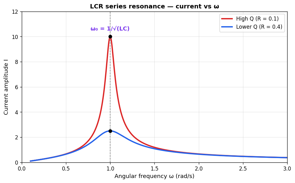
Study the LCR resonance curve and answer:
The resonance frequency of a series LCR circuit is:
Aω₀ = 1/(LC)
Bω₀ = 1/√(LC)
Cω₀ = √(LC)
Dω₀ = LC
At resonance, the impedance of a series LCR circuit is:
AMaximum
BMinimum (= R)
CZero
DInfinite
Explain the importance of Q-factor in resonance.
Show answersHide answers
1. Option 2 — ω₀ = 1/√(LC)
2. Option 2 — Minimum (= R)
3. In a series LCR circuit, the impedance is Z = √(R² + (X_L − X_C)²) where X_L = ωL and X_C = 1/(ωC). At resonance ω₀ = 1/√(LC), X_L = X_C so Z = R (purely resistive, minimum). Current I = V/Z is maximum at resonance. The sharpness of resonance is described by the quality factor Q = ω₀L/R = (1/R)√(L/C). High Q → narrow, sharp peak (selective). Low Q → broad peak. Used in tuning circuits (radios — only the station at the resonant frequency is amplified), filters, and oscillators. The phase between V and I changes from leading (capacitive) below resonance to lagging (inductive) above resonance.